Project Goal
For our Capstone project, we built a multi-protocol IoT honeypot designed to help students understand modern home-lab security and how easily common IoT protocols can be explored or abused when controls are weak. The goal was to create a realistic-looking device that could safely log attacker-style interactions and turn them into something instructors and students could learn from in a controlled environment.
Hardware & Architecture
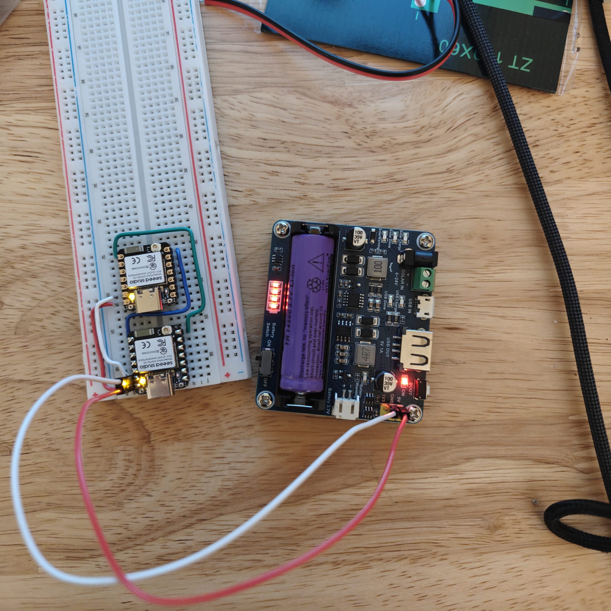
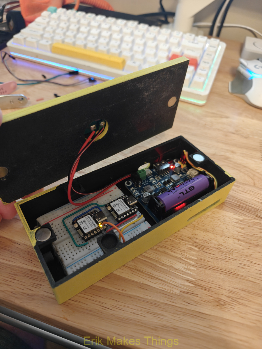
A key design constraint shaped the entire build: the Seeed Studio XIAO ESP32-C6 can’t run 2.4 GHz Wi-Fi and Zigbee (802.15.4) at the same time. To solve this, we split the honeypot into two identical ESP32-C6 boards.
- Bottom board: Dedicated Zigbee coordinator with intentionally weak security to encourage join attempts. It converts Zigbee events into small JSON objects and sends them to the top board over UART.
- Top board: Acts like a multi-protocol gateway. It connects to Wi-Fi, exposes an HTTP dashboard, interacts with an MQTT broker, advertises a believable BLE GATT profile, and logs events from all four protocol surfaces (HTTP, MQTT, BLE, Zigbee).
Designing the Enclosure
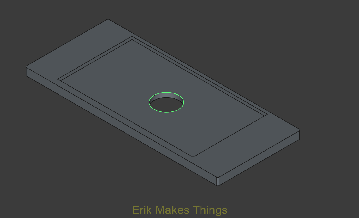
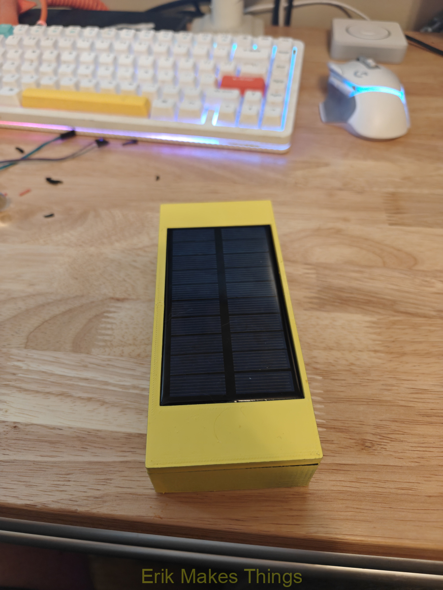
To make the honeypot practical and portable, I designed a custom case in FreeCAD around the boards’ dimensions and mounting needs. The enclosure was 3D printed in HYPER-PLA on my Ender 3. To simplify maintenance, I included magnet-based snap-fit closure using 10 mm × 3 mm magnets instead of screws. I also integrated a lid mount for a small 5 V solar panel, then finished the chassis with a yellow paint job and honeycomb theme to visually reinforce the “honeypot” identity during demos.

How it works
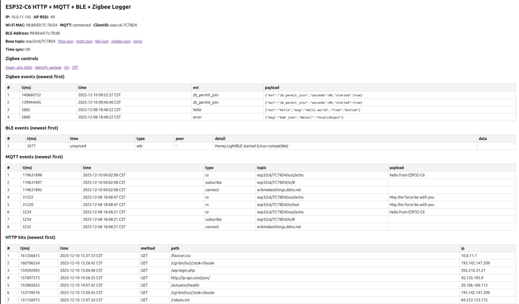
The top board is where the honeypot feels like a real device to an attacker. On boot, the firmware starts serial, connects to Wi-Fi, configures time using NTP, initializes the HTTP server, MQTT client, BLE stack, and then brings up the Serial1 UART link to the Zigbee board. It also generates a short unique ID based on the board’s MAC address so multiple nodes can be deployed without manual topic configuration. It then continuously services HTTP requests, processes MQTT traffic, and reads Zigbee JSON messages from the UART link.
Because the microcontroller has limited memory, the system avoids long-term storage and instead uses separate ring buffers for each protocol. Each buffer stores the most recent 50 events, overwriting older entries as new ones arrive. Every entry includes a timestamp, event type, and protocol-specific details such as HTTP path, MQTT topic/payload, BLE address, or Zigbee
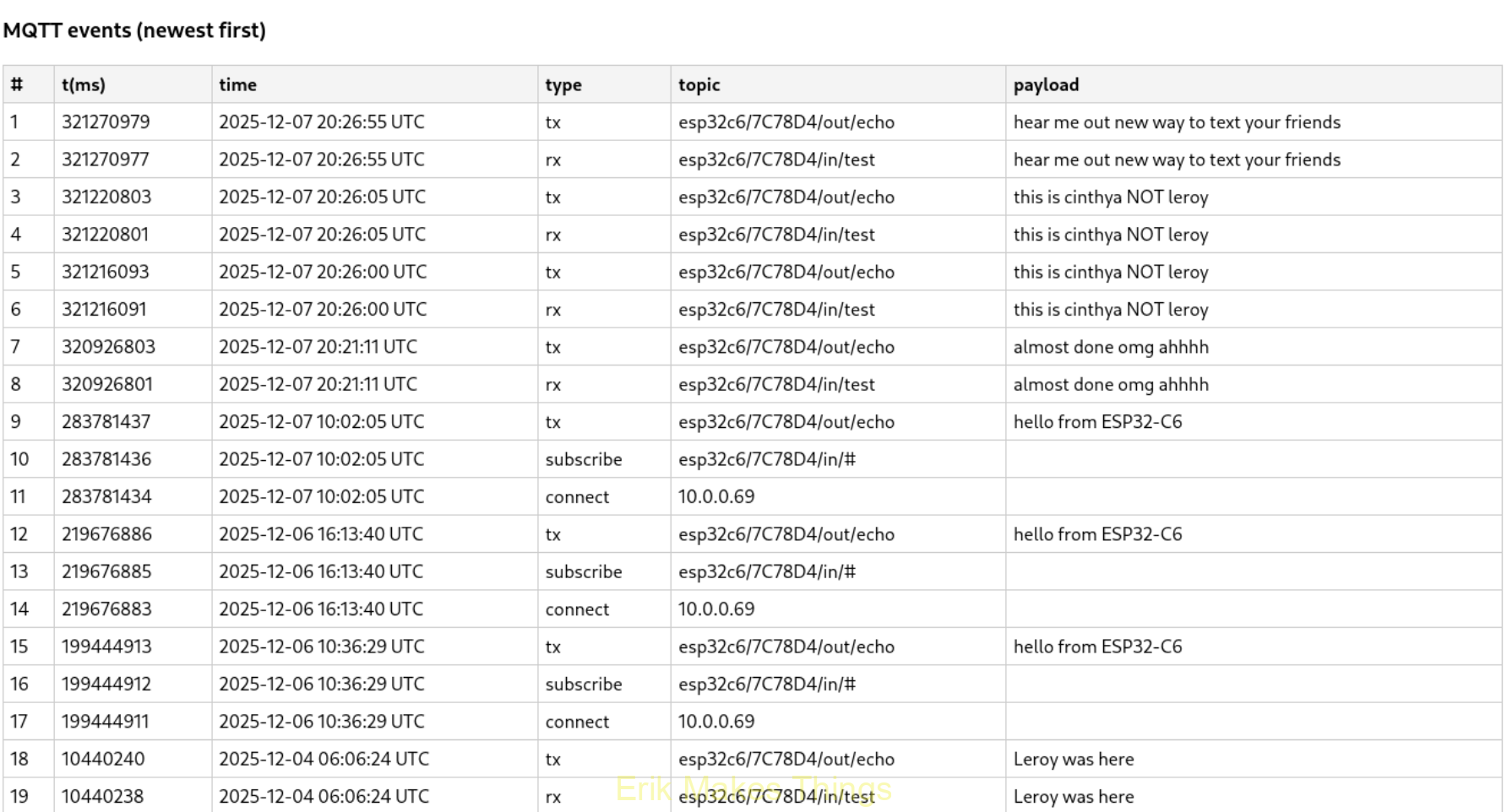
The MQTT component is designed to look believable to scanners and testers. The top board connects to a broker on the core VLAN, builds a client name and topic prefix from its MAC-derived ID, publishes an “online” status message, and subscribes to an input topic pattern. When messages arrive, a callback logs the event and echoes the content back to an output topic.
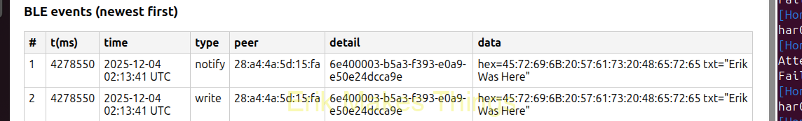
For BLE, the device uses the NimBLE stack to present as a plausible smart device named “Honey-LightBLE.” The advertised services include familiar standards like Device Information and Battery Service alongside a fake configuration-style service. Read/write callbacks record which characteristic UUID was accessed, the client’s BLE address when available, and both hex and ASCII representations of any data written. If a client writes to a state-like characteristic, the honeypot sends a notification back to simulate a real device response.
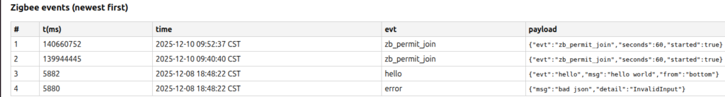
Rather than trying to merge all radios onto one chip at once, Zigbee events are forwarded from the bottom board using a clean, simple UART protocol. The top board reads Serial1 until it sees a newline, then attempts to parse the line as JSON. If the object contains an “evt” field, it is logged into the Zigbee ring buffer; if parsing fails, the firmware logs an error event instead.
The bottom ESP32-C6 is dedicated to Zigbee. Its setup initializes debugging serial, the UART link, LED state, and sends early “boot/hello” style events for quick verification from the top board’s dashboard. Zigbee logic runs inside a separate task (esp_zb_task), keeping the coordinator responsibilities isolated from the multi-protocol gateway functions.
Setting Up the Lab
To keep the project realistic but safe, I built a dedicated testing environment on my home network using VLAN segmentation on my UniFi gateway. The lab was designed so our team could run recon and protocol testing against the honeypot without putting my everyday devices or core services at risk. The structure also reflects how an enterprise would isolate IoT systems to reduce lateral movement and limit blast radius if a device becomes compromised.
I created three main network segments. The core VLAN (10.0.0.x) hosts my critical services, including my main Ubuntu server (“wifu-server”) running Docker containers like my web server and Home Assistant, as well as a separate DNS cache server. The IoT VLAN (10.0.11.x) is used exclusively for testing and contains the honeypot plus several real IoT devices such as a Litter-Robot 4, an Ecobee thermostat, and a wired Philips Hue bridge and bulbs. The main VLAN is reserved for personal devices (laptops, phones, TVs, etc.) and is intentionally out of scope to keep experimental traffic away from my daily-use equipment.
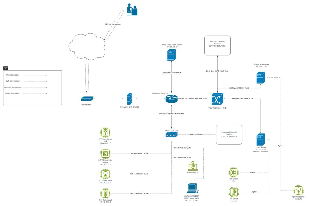
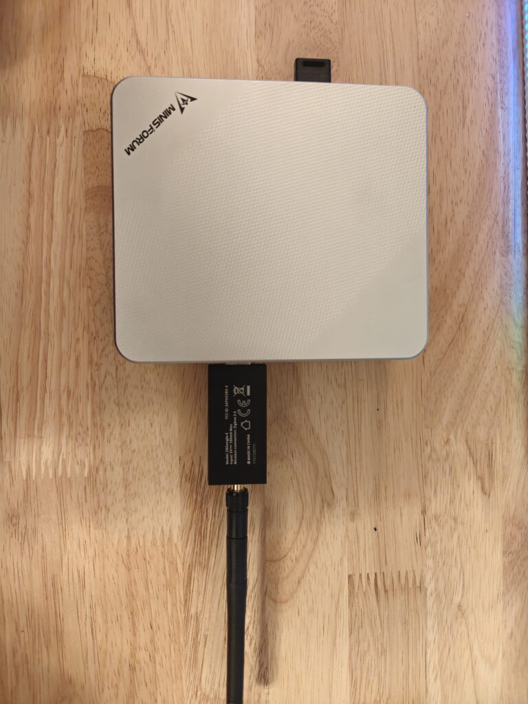
From there, I added routing and firewall rules to expose only what we needed for testing. A key part of the lab design was enabling controlled team access to an attacker workstation without opening default high-noise ports to the internet. To achieve this, I configured port forwarding from my public IP to a dedicated attacker machine: a Minisforum UN150P running Kali on the IoT VLAN. External requests are mapped to RDP on port 6767 and SSH on port 6768, allowing remote access while avoiding standard ports like 3389 and 22. This approach keeps access practical for teammates while reducing basic opportunistic scanning risk.
On the services side, I installed an MQTT broker on my home server and configured it for anonymous access so the honeypot and test devices could publish/subscribe without needing per-device credentials. This setup was intentional for education: it increases realism for “weak default” demonstrations and makes it easier to reproduce attacks and logging outcomes during testing.
To make the Kali box usable for the whole team, I installed a full desktop environment along with xrdp and OpenSSH so teammates could connect either through remote desktop or terminal. I also created separate user accounts for Jesse and Cynthia, which avoided password sharing and made activity more traceable during collaboration.

Recon and MQTT
Cynthia led our recon and MQTT testing, validating that the honeypot was discoverable and behaved like a believable IoT target inside the segmented home lab. She used Nmap to identify MQTT-related exposure and confirm the messaging surface.
After discovery, she used curl to pull useful HTTP-visible details, including the connected broker, ClientID, and base topic structure; exactly the kind of information that makes MQTT hijacking and message injection easier.
For MQTT exploitation and validation, Cynthia used Mosquitto tooling to simulate message injection/broker-style interaction and confirm our logger captured the traffic as expected. She also incorporated RALMQTT as part of her MQTT pentesting toolkit, which we referenced alongside our broader MQTT testing sources.

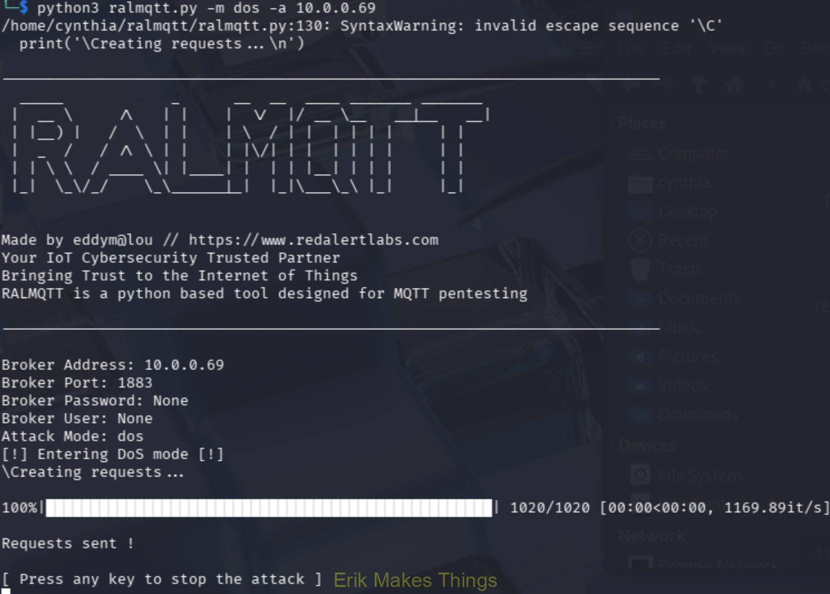
To round out the risk story, she performed a SlowITe-style MQTT denial-of-service demonstration, showing how TCP-based IoT messaging can be disrupted through connection exhaustion even with minimal bandwidth.

BLE Testing
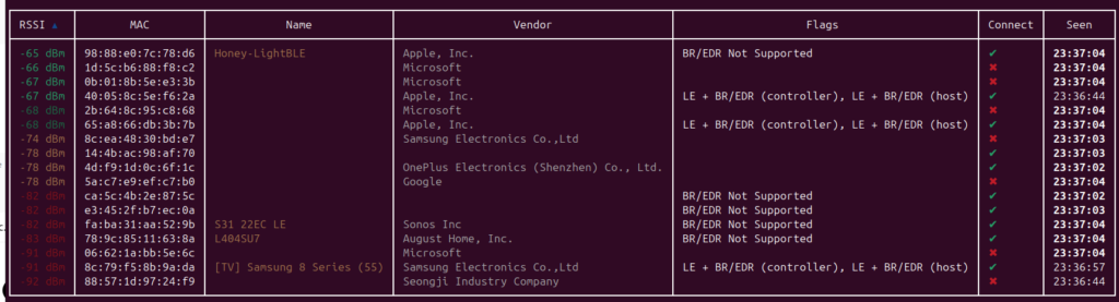
I led the BLE testing to confirm the honeypot presents a believable Bluetooth target and reliably logs both passive probing and active interaction. I started by scanning for nearby devices using Bettercap’s ble.recon module, which gave me a quick snapshot of the BLE environment and helped me confirm Honey-LightBLE was advertising as expected based on name, RSSI, and vendor details.
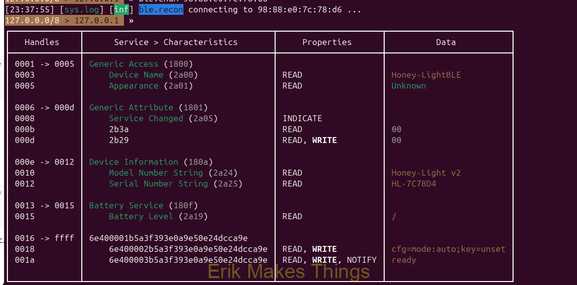
After identifying the device, I connected and queried its GATT profile. The honeypot exposed standard services like Generic Access, Device Information, and Battery, plus a custom Nordic UART-style service. While exploring the GATT table, I confirmed that even simple reads generated visible events in my dashboard, which showed the system could capture low-noise reconnaissance.

To test active input, I used bluetoothctl to connect and write a short payload to a writable UART RX-style characteristic. The dashboard logged and decoded the write, validating the full chain from discovery, connection, GATT enumeration, write action, and finally event capture. This confirmed the honeypot can reliably record both read-style recon and write-based injection behavior.


Zigbee Testing
Jesse led our Zigbee testing to validate that the Zigbee side of the honeypot functioned correctly and to establish what normal baseline traffic should look like in a small smart-home style environment. He noted that meaningful “attack-style” testing was harder to demonstrate in a clean way because Zigbee’s behavior is highly local and device-driven, so most of the effort focused on observation and recon rather than flashy exploitation.
During this phase, the Zigbee network was confirmed to be working and able to pair with Zigbee end devices, which helped verify the core functionality of the setup.
Jesse also documented a limitation we ran into: issues with the Zigbee logger prevented us from showing the depth of logs we originally intended. Even so, we were still able to capture and confirm devices attempting to connect to the system, which supported the overall purpose of the Zigbee-facing honeypot design.
Download the code to try for yourself.


Very nice!